CISSP Blog Post 26, Domain 8: Malware


Credit: Post based on CISSP course presented by Dennis Lee, November 2018

Finally! Congratulations on making it to the last CISSP post in this series. Today we will cover the most exciting topic of Malware! Here are some of the most common types of malware you need to know about:

  1. Viruses are malicious code that replicate by creating, replacing, or attacking other programs or files. Viruses generally require some initiating action by the user. Virus Types include File Infectors and Boot Sector Infectors (which are read before the host operating system is started)
  2. Worms are a malicious and continuous process that reproduces and eats up resources. Generally it does not require an initiating action by the user. They spread over networks by exploiting vulnerabilities in network protocols, or through application components (e.g. DLLs, etc.) Unlike viruses, worms do not require using infected files to spread (i.e. viruses require a file “host”).
  3. Trojans are installed by a user because they think they want it. They are a form of social engineering.
  4. Remote Access Tools aka RAT’s can be legitimate remote administration tool but they can also be an illegitimate remote access trojan.
  5. Rootkits are often trojans or other malware that can replace critical system files or interfere with system kernel functions to seize control of a processor’s central ring (0 or 1) such that a whole system is compromised.
  6. A Logic Bomb is malicious code, often planted by someone you know (i.e. an insider programmer) that is triggered by an event or specific schedule. Usually as an act of revenge.
  7. Botnets are where multiple systems are compromised and turned into agents / bots / zombies.
  8. Distributed Denial of Service (DDoS) attacks have 3 phases:
    1. Attacker infects many machines with agents (aka bots or zombies)
    2. Attacker uses a Master / Handler program to command agents
    3. Agents initiate denial of service or SPAM attack against attacker’s target ISPs and managed DNS can help stop a DDoS attack.
  9. Zero-Day Exploits / Malware are attacks that take place shortly after a security vulnerability is discovered but before a vendor has a fix or patch available.

So how do you protect against Malware? Malware tools come with different types of capabilities including:

  • Known Signature Scanning – the program scans based on known malware or attack signatures (e.g. Antivirus). These solutions are only as good as known, available signatures.
  • Heuristic Scanning – the program looks for suspicious system behavior or activity. It does NOT use baseline learning, it only uses predefined rules.
  • Change Detection Tools look for unauthorized changes to files, system configuration, or programs (e.g. File Integrity Monitoring solutions). These tools take baseline snapshots of files (via a file hash) and then creates new hashes periodically to see if they change.

CISSP Blog Post 25, Domain 8: Program Exploits


Credit: Post based on CISSP course presented by Dennis Lee, November 2018

Ok! Last domain of the CISSP – we have two topics to cover – we’ll cover one today and one next week.

In this post, we’ll cover some common Program Exploits at a high level to get you familiar with terminology.

The first is Memory Buffer Overflow an example is a website form running on a server where the attacker enters a longer string than the program that ingests the form can allow, causing the memory on the server to overflow which can corrupt data, crash the system, or provide access to things the attacker should not have access to. To fix, the programmer must put in validation checking for fields in the website form.

Covert Channel is a secret transfer or sharing of information that violates security. Examples could be a Covert Storage Channel which is a hidden data storage location, or hidden data that an attacker shouldn’t be accessing within a program. A Covert Timing Channel is secret signaling. For example, using screen flicker to exfiltrate data from a facility.

Cross-Site Scripting is a well known attack and is where a malicious user puts comments with a malicious script in a web form. A regular user then picks up content when they load the website in their browser and the comment causes the regular user’s browser to execute the script. This for example, could be used to harvest cookies. A user can safeguard against this by disabling scripting in their browser.

Cross-Site Request Forgery is similar where a user has two browser tabs open. In Tab 1 they might have an image with a reference link or a script with a request action on a specific banking site. In Tab 2, they may have open their banking site. The browser may allow a transaction or activity from Tab 1 to occur on the website in Tab 2 believing it’s legitimate because it’s occurring within the same browser.

Memory or Object Reuse is where you need to sanitize media before reusing it with a protected audit log trail.

Trapdoors / Back-doors / Maintenance Hooks are hidden mechanisms for bypassing access controls. They are put in by programmers – typically for convenience when debugging their code.

SQL Injection is where a front-end form passes input containing SQL code that runs on a back-end database and returns output or runs code. For example, if someone put the following into a "First Name" field of a web form: “Bobby ‘DROP TABLE”, it could cause the database to delete a table from the database if there are no validation checks or neutralization of form entries to cause them to not execute.

A Race Condition Attack is where two signals or processes race each other to influence the output first. A physical representation of this would be two joint bank account owners trying to make a withdrawal from the account at the same time. If the combination of both their withdrawals is larger than the account, the bank may not realize that they have overdrawn their account and allow both of them to complete their withdrawals at the same time.

Time of Check / Time of Use (TOCTOU) is where variables of a system are changed but there’s a delay in when the system honors the changes. The example here is changing your account permissions may not take affect right away or require you to refresh your browser, etc.

Recovery vs. Restoration

CISSP Blog Post 24, Domain 7: Disaster Planning and Restoration


Credit: Post based on CISSP course presented by Dennis Lee, November 2018

Ok, you’ve (hopefully) backed up your data in the last post, so now let’s talk Disaster Planning and restoration.

Some unforeseen factors when planning that you should be aware of may include:

  • Your backup site is also impacted by the disaster
  • You cannot get to your backup site
  • If you have a hot site, it may not be able to accommodate multiple customers all having an issue at the same time
  • Your employee’s families may need care as well, reducing available support staff

So what’s the goal of restoration? The goal is to return to your original site with original capacity and data.

Recovery vs. Restoration

Restoration phases include:

  1. Is the incident ended?
  2. Is it safe to return?
  3. Document the losses
  4. Salvage the assets
  5. Repairs & replacement
  6. Return to site (Tier 5 first, all the way up to Tier 1 support employees)
  7. Closure – lessons learned, official end of disaster

Pro tip: When you’re documenting your plan put a 1-year expiration date on the plan to force updates and make it obvious which is most recent version.

Speaking of version control – obsolete plans should be:

  1. Archived
  2. Collected
  3. Confirm collection
  4. Issue new plan
  5. Destroy old plans

Oh… also you – need to be testing your plan. You can do so in multiple ways including:

Testing Type Method
Checklist or Desk Check Give each business unit (BU) a copy of the plan and have them run through a checklist to ensure all relevant points are covered.
Structured Walk-through / Tabletop Exercise Key players get together and review plan collectively.
Simulation Test Practice drill mobilizing the personnel (e.g. Fire Drill) and rehearse going to assembly point.
Parallel Test Operational test at alternate site running in parallel with main site (production).
Full Interruption Test Shutdown production environment and run a live environment at alternate site. Need to have prior management written permission before parallel test conducted.

CISSP Blog Post 23, Domain 7: Digital Backups


Credit: Post based on CISSP course presented by Dennis Lee, November 2018

Welcome to February 2021! This month I plan to wrap up our CISSP blog post series.

Let’s start by talking about data backups! There are lots of ways to do data backups:

  • A Full backup is exactly what it sounds like – all your data is copied to another location and backed up.
  • A Differential backup is where all data that’s changed since the last full backup is copied.
  • An Incremental backup is where all data that has changed since the last full OR incremental backup, is backed up. This is easier to restore from but you will need more time and media storage space.
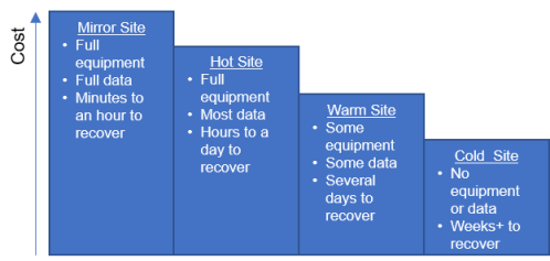
Cost and Capability Comparison of Backup Sites

Some technology that can be useful for creating backups is a Redundant Array of Independent Disks (aka RAID). Again, lots of choices:

RAID 0 – Stripping of data – very fast, no recovery! 2 drives minimum required.

RAID 0
RAID 0

RAID 1 – Mirroring – double storage cost, slower, 2 drives minimum required.

RAID 1
RAID 1

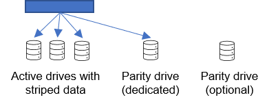
RAID 3 & 4 – RAID 3 reads and writes data at the byte level. RAID 4 reads and writes at the block level. You can only lose 1 active drive at a time. If the parity drive fails, the RAID falls back to RAID 0 or you can rebuild the parity drive back on a spare drive. This requires 3 drives minimum and only gives 2 drive capacity.

RAID 3 & 4
RAID 3 & 4

RAID 5 is faster because parity info is written in parallel. If there is no spare drive, it will reconstruct lost data and parity info into system memory in chunks. It needs 3 drives minimum, with a 2 drive capacity.

RAID 6 (Enhanced RAID 5) provides 2-dimensional parity, allowing for the loss of 2 drives simultaneously. It needs 1 extra drive than a RAID 5. Requires 4 drives minimum, with a 2 drive capacity.

RAID 5 & 6
RAID 5 & 6

You can also combine RAID’s: e.g. 0+1, 1+0, 1+5, 5+1, etc.

CISSP Blog Post 21, Domain 4: Network Tunneling


Credit: Post based on CISSP course presented by Dennis Lee, November 2018

Network tunneling is where two networks are connected to one another over the public internet. This is accomplished through different protocols including:

Point-to-Point Protocol (PTPP) which can be used with different authentication options. Adding / removing frames is called “tunneling”.

Point-to-Point Protocol (PTPP) Tunneling

The Password Authentication Protocol (PAP) uses an ID and password to authenticate users, however passwords are sent in clear-text.

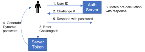
There are lots of versions of the Challenge-Handshake Authentication Protocol (CHAP), a common one is MD5-CHAP. CHAP provides for repeated / continuous authentication if desired to re-authenticate a client on a set time period (i.e. every 4 hours) to reduce risk of spoofing and session hijacking. In the standard version of CHAP, passwords are stored in clear text on the server, leaving it up to the implementation vendor on how to protect those passwords.

The CHAP Challenge number is typically a randomized session ID issued for tracking each user. The Nonce (short for “Number Used Once”) is typically a time-based session ID, only used once (timestamp) to reduce the risk of password replay attacks.

Challenge-Handshake Authentication Protocol (CHAP) Process

The Extensible Authentication Protocol (EAP) can be used with passwords, challenge and response (e.g. CHAP), biometrics, tokens, combining protocols (e.g. EAS+TLS), device authentication, etc.

Layer 2 Tunneling Protocol (L2TP) is a hybrid of L2F and PPTP. PPTP was developed by Microsoft, PPTP uses PPP frames but provides encryption. L2F was developed by Cisco and also uses PPP frames but does not have encryption. However, each tunnel can support multiple connections per user. L2F requires special hardware to use it.

Microsoft & Cisco worked together to combine L2F and PPTP into L2TP. L2TP uses PPP frames, supports multiple connections in a single tunnel, does not require special hardware, but also does NOT provide encryption.

IPSec is a protocol designed to protect IP traffic through use of an:

  • Authentication Header (AH) which is designed to authenticate source IP addresses, and
  • Encapsulating Security Payload (ESP) which provides encryption of both payload and header if desired.

Security Associations (SA’s) are one-way connections using either AH or ESP services. Each SA is uniquely identified using a:

  • Security Parameter Index (a session ID for tracking connection)
  • Destination IP address
  • AH or ESP identifier A second SA must be defined for 2-way communication.

End-to-end encryption / Transport Mode is where only the payload portion of a packet is encrypted (if using encryption).

Two examples of this include: Transport Mode with ESP

Transport Mode with Encapsulating Security Payload (ESP)

And Link Encryption / Tunnel Mode – this is where the entire original packet is encrypted including the original header and payload. It is also known as a Gateway-to-Gateway VPN. A trick to help you remember it is <u>Linc</u>oln Tunnel -> Tunnel Mode uses <u>Link</u> Encryption

Here’s an example of Tunnel Mode with ESP:

Tunnel Mode with Encapsulating Security Payload (ESP)

To summarize:

Tunneling Protocol Provides Encryption?
IPSec Yes, ESP
SSH Yes
L2F No
L2TP No, but yes if partnered with IPSec
PPTP Yes
MPLS No
TLS/SSL Yes
PPP No

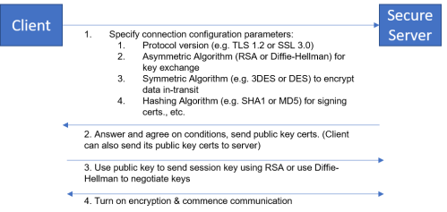
To end our discussion about the OSI model, we’ll touch briefly on how Transport Layer Security (TLS) and Secure Sockets Layer (SSL) work:

TLS/SSL Connection Negotiation Process

CISSP Blog Post 19, Domain 4: Network: OSI Layers 5 (Session Link) & 6 (Presentation)


Credit: Post based on CISSP course presented by Dennis Lee, November 2018

Layer 5 protocols coordinate the orderly exchange of information. They include:

The Remote Procedure Call (RPC) Protocol which is utilized in client-server environments and Secure RPC which uses mutual authentication for client & server to authenticate one another.

Remote Procedure Call (RPC) Protocol Process

Layer 6 protocols are responsible for giving applications access to the network services, i.e. they help applications talk to the network. An example is Microsoft Outlook using Layer 6 protocols such as SMTP, POP3, or IMAP to handle email transmission on the network. Other examples include:

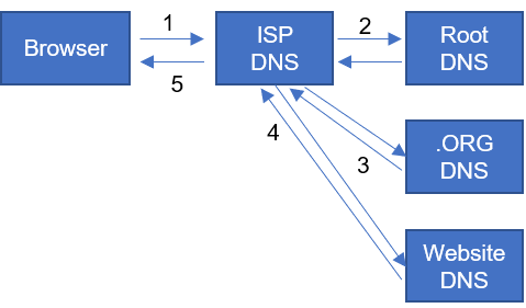
The Domain Name System (DNS) protocol which is a translation service to resolve Fully Qualified Domain Names (FQDN) to IP addresses. The way this works is:

  1. Browser sends domain to ISP for lookup
  2. ISP DNS goes through recursive search, first to Root DNS, which will return local .ORG DNS address
  3. .ORG DNS will return IP address of DNS server of actual website Website
  4. DNS server will return IP address of actual website to ISP DNS
  5. ISP DNS then returns actual website IP address to Browser
Domain Name Service (DNS) Lookup Process

DNS Security (DNS-SEC) is a protocol designed to combat DNS cache poisoning using digital signatures to verify that DNS data is coming from authentic sources.

Network Address Translation (NAT) is the translation between public internet IP addresses and local (private) IP addresses. Private IP ranges include:

  • 10.0.0.0 – 10.255.255.255
  • 172.16.0.0 – 172.31.255.255
  • 192.168.0.0 – 192.168.255.255
Network Address Translation (NAT)

CISSP Blog Post 18, Domain 4: Network OSI Layer 4, the Transport Layer


Credit: Post based on CISSP course presented by Dennis Lee, November 2018

First off, Happy New Years! Hopefully your New Year’s resolution was to continue to study for the CISSP exam! 😉

Today we’re going to look at Layer 4 protocols which are responsible for end-to-end, host-to-host, or source-to-destination communications. Common protocols here include the:

Transmission Control Protocol (TCP) which is a connection-oriented protocol, i.e. it expects acknowledgments from the destination.

TCP Handshake
TCP Handshake

The sequence number increments by the size of bytes in the packet. To close transmission, device A send a final ACK transmission and then sends FIN with the last sequence it is up to:

TCP Communication Close

TCP Headers are sandwiched between the IP Header and the Data Payload. They typically include:

  • Source & Destination Ports
  • Sequence #’s
  • Acknowledgement #’s
  • Flags
  • Checksums
  • Etc.

Well known port numbers range from 0 to 1023. Examples are:

  • HTTP = 80
  • SMTP = 25
  • FTP = 20 & 21
  • Telnet = 23
  • SSH = 22
  • DNS = 53
  • HTTPS = 443

Ports indicate the protocol being used. The sequence # and checksum are used to figure out if a packet needs to be resent.

User Datagram Protocol (UDP) is a connection-less protocol, i.e. it does not expect acknowledgements and does not have any error checking. It assumes best effort and there is no connection “state” for a firewall to observe / monitor. The UDP header only includes source and destination ports, checksum, etc.

Two common TCP exploits at the OSI Layer 4 level include the

TCP Sequence Number Attack

TCP Sequence Number Attack

SYN Flood Attack

SYN Flood Attack
SYN Flood Attack

FFMpeg Command Line (DOS CLI) Tricks


Today’s post is off topic from cybersecurity. I’ve been playing around with FFMpeg to batch convert some video and audio files and want to share some tricks I’ve learned for both FFMpeg and the Windows DOS command line.

While I was researching how to do some of these commands, I found a lot of conflicting advice that was for using Linux command lines, etc. so to be clear, this is for the Windows DOS command line only! I make no guarantees this will work on other systems.

Okay, the common scenarios I’m going to show you how to work with today include:

  1. Using FFMpeg to convert a video file to an H.264 video format while copying the audio as is
  2. Iterating through a folder of video files and converting them as in #1
  3. Using FFMpeg to show the video and audio codec information of a file
  4. Iterating through a folder of files to show the video or audio codec information of all the files
  1. Using FFMpeg to convert a video file to an H.264 video format while copying the audio as is

ffmpeg -i movie.mkv -c:v libx264 -preset slow -crf 17 -tune film -c:a copy converted-movie.mkv

Breaking this command down:

ffmpeg = call the program

-i = designate the input file

movie.mkv = this is the original source file that you want to convert

-c:v = command to copy video

libx264 = H.264 encoding library to use

-preset slow = a preset is a collection of options that provides a certain encoding speed to compression ratio

-crf 17 = Constant Rate Factor. CRF stipulates the rate control mode to keep the best quality vs. file size. This is the recommended rate control mode for most uses. This method allows the encoder to attempt to achieve a certain output quality for the whole file when output file size is of less importance. This provides maximum compression efficiency with a single pass. By adjusting the so-called quantizer for each frame, it gets the bitrate it needs to keep the requested quality level. The downside is that you can’t tell it to get a specific file size or not go over a specific size or bitrate, which means that this method is not recommended for encoding videos for streaming.

The range of the CRF scale is 0–51, where 0 is lossless, 23 is the default, and 51 is worst quality possible. A lower value generally leads to higher quality. 17 or 18 is close to visually lossless and should look the same or nearly the same as the input but isn’t technically lossless. The range is exponential, so increasing the CRF value +6 results in roughly half the bitrate / file size, while -6 leads to roughly twice the bitrate. Choose the highest CRF value that still provides an acceptable quality. If the output looks good, then try a higher value. If it looks bad, choose a lower value.

-tune film = allows you to change settings based upon the specifics of your input. For example, if your input is animation then use the animation tuning, or if you want to preserve grain in a film then use the grain tuning. If you are unsure of what to use or your input does not match any of the available tuning options then omit the -tune option. You can see a list of available tuning options with -tune help, and what settings they apply with x264 --fullhelp.

-c:a copy = copy audio as is, no changes

converted-movie.mkv = this is the new name of the converted video file

2. Iterating through a folder of video files and converting them as in #1

To iterate through a folder full of video files and convert them all simply wrap the above command in a DOS FOR loop

for %a in (*.mkv) do ffmpeg -i "%a" -c:v libx264 -preset slow -crf 17 -tune film -c:a copy "converted-%a"

Ok, couple of new things going on here:

for = begin for loop

%a = DOS parameter placeholder for each file in the folder

in (*.mkv) = this delineates the “set” of objects for the for loop to iterate over. It says for all MKV files in the current folder apply (do) the ffmpeg command.

"converted-%a" = again, same as above, instead of having to stipulate the output name of each file, it simply takes the name of each file and prepends “converted-” to the front of it and saves it in the same folder. When you wrap a parameter in quotes, it will account for delimiters such as spaces in a file name.

3. Using FFMpeg to show the video and audio codec information of a file

For video: ffprobe -v error -select_streams v:0 -show_entries stream=codec_name -of default=noprint_wrappers=1:nokey=1 FILE_NAME.HERE

For audio: ffprobe -v error -select_streams a:0 -show_entries stream=codec_name -of default=noprint_wrappers=1:nokey=1 FILE_NAME.HERE

These are virtually the same, the only difference is stipulating that you want to select the 1st (0th) element of the video or audio codec (v:0 or a:0). Breaking these down:

ffprobe = this is a ffmpeg utility to analyze a media file

-v error = this suppresses display of the ffprobe version information. Not necessary to get the codec information that we want, but makes a much cleaner output that’s easier to read.

-select_streams v:0 or a:0 = this flag tells ffprobe which video or audio stream you want to view the codec information for. If your file has more than one, you will need to change the 0 to a 1, 2, etc. The default that you’re usually interested in though is the first (or 0th) stream.

-show_entries = flag to print the codec information to the screen

stream=codec_name = instruction to ffprobe to tell it that we want to know what the name of the codec is

-of = flag to specify the default output format

default=noprint_wrappers=1:nokey=1 = these are key value pairs of “writers” that ffprobe will use to output information to the screen. noprint_wrappers stipulates to print or not print the section header. A value of 0 stipulates to print, a a stipulates to not print. The nokey stipulates to print or not print the key value of each field. Again, A value of 0 stipulates to print, a a stipulates to not print. In this case, we’re suppressing printing of anything beyond the codec name. I encourage you to play around with these values to see what other information is available.

FILE_NAME.HERE = This is a placeholder for the file that you want ffprobe to provide information about.

4. Iterating through a folder of files to show the video or audio codec information of all the files

For video: for %a in (*.*) do ffprobe -v error -select_streams v:0 -show_entries stream=codec_name -of default=noprint_wrappers=1:nokey=1 “%a”

For audio: for %a in (*.*) do ffprobe -v error -select_streams a:0 -show_entries stream=codec_name -of default=noprint_wrappers=1:nokey=1 “%a”

This is the same as #2 above where we use a FOR block to iterate through all the files in a folder to display the codec information for each file. If there are a mix of file types (e.g. video & audio together), than these may fail on a file that does not have a video or audio stream.

I hope this helps you – I know for myself that figuring out the for loops to work with spaces in file names, etc. was a real challenge getting the syntax correctly. If you find a better way or an error in any of my work please tell me in the comments below!

Helpful resources that I used in compiling this post:

  1. https://trac.ffmpeg.org/wiki/Encode/H.264
  2. https://catswhocode.com/ffmpeg-commands/
  3. https://ffmpeg.org/ffprobe.html

CISSP Blog Post 17, Domain 4: Network: OSI Layers 2 (Data Link) & 3 (Network)


Credit: Post based on CISSP course presented by Dennis Lee, November 2018

Not going to spend a lot of time on OSI Layer 2, aka the Data Link Layer. At this layer, protocols are responsible for node-to-node or link-to-link communications between systems on the same network

Common protocols include:

  • Address Resolution Protocol (ARP) which resolves IP addresses to MAC addresses. It is susceptible to ARP cache poisoning attacks.
  • Multiprotocol Label Switching (MPLS) operates at both L2 and L3 of the OSI model. In summary, data enters the MPLS network through a Label Edge Router which passes traffic to Label Switch Routers until data gets to the final Edge Router and exits the MPLS network to the destination. MPLS routers add special encapsulating data labels to send data along pre-defined network paths. The Switch routers forward data along the directed path, where the last edge router strips off the labels before the data exists the network.

The OSI Layer 3, Network Layer protocols are responsible for network-to-network, router-to-router, or gateway-to-gateway communications and include:

The IP Protocol (IPv4) handles IP addressing. Without going into the difference between the two, the main reason IPv6 was developed is because IPv4 has literally run out of addressable addresses to assign to Internet devices.

  • IPv4 = 32-bit addresses which provide 2^32 addresses
  • IPv6 = 128-bit addresses which provides 2^128 addresses

The IP protocol handles data fragmentation and reassembly of packets if you’re sending over networks with different maximum transmission unit (MTU) sizes. The IP header element includes items such as:

  • Total fragment length
  • Fragment ID
  • Different flags
  • Fragment offset
  • Time-to-live
  • IP source address
  • IP destination address
  • Etc.

The Internet Control Message Protocol (ICMP) can be abused to conduct Man-in-the-Middle (MITM) and Denial of Service (DoS) attacks. It provides network diagnostics (such as ping, traceroute, etc.) and network error reporting. It also provides ICMP redirect functionality where a router can inform a sender of a better route to the final destination.

A couple of common Layer 3 attacks include the:

  • Tear Drop Attack which crashes a system by exploiting the fragment offset field to overload the receiving system with malformed packets.
  • SMURF Attack where an ICMP echo request is sent to the network broadcast address of a spoofed victim, causing all nodes to reply to the victim with echo reply. A similar attack called a FRAGGLE attack uses the UDP protocol to create a similar effect.
SMURF Attack Process